 Ano
AnoGuide · Dimensions
Anodizing Thickness and How It Changes Your Dimensions
Anodizing grows partly into the surface and partly out of it, so a finished part is larger than the machined part by roughly half the coating thickness per surface. On a Hard Coat that is enough to close a bore. Here are the numbers and what to put on the drawing.
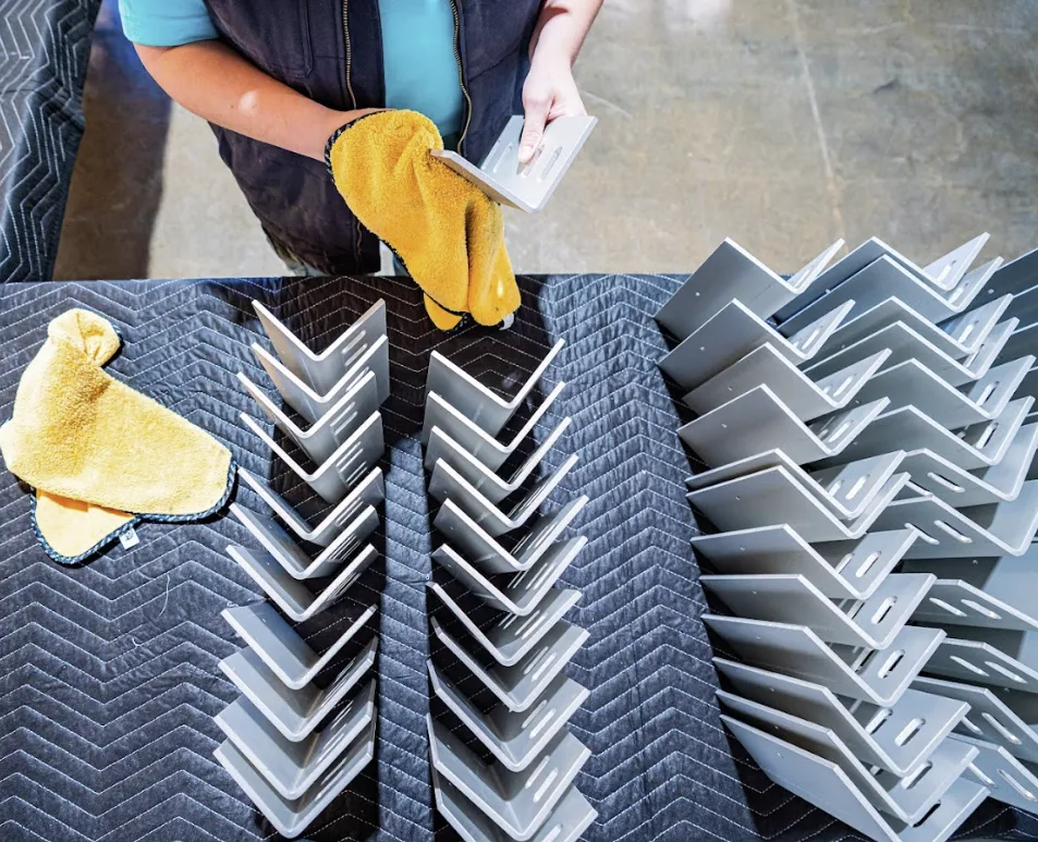 INSPECTION · EVERY BATCH
The Rule in One Sentence
For every surface, the part grows outward by roughly half the total coating thickness, and the other half is consumed from the metal that was already there. Engineers call these build-up and penetration, and the approximate fifty-fifty split holds well enough for design work on both Type II and Type III.
The consequence people miss is what happens across a dimension rather than on a face. A shaft grows on both sides, so its diameter increases by about the full coating thickness. A bore closes on both sides, so its diameter decreases by about the full coating thickness. On a flat plate, each face grows by half, so overall thickness increases by about the full amount too. The number to plan around is therefore usually the whole coating thickness, not half of it.
| CALLOUT | TYPICAL THICKNESS | GROWTH PER SURFACE | WHERE IT MATTERS |
|---|---|---|---|
| Type II, Class 1 (clear) | 0.0001 to 0.0007 in | About 0.00005 to 0.00035 in | Rarely, except on close fits |
| Type II, Class 2 (dyed) | 0.0002 to 0.001 in | About 0.0001 to 0.0005 in | Close-tolerance bores and pins |
| Type III Hard Coat, thin | 0.0005 to 0.001 in | About 0.00025 to 0.0005 in | Most sliding fits |
| Type III Hard Coat, standard | 0.002 in nominal | About 0.001 in | Nearly every fit and thread |
| Type III Hard Coat, heavy | 0.003 to 0.004 in | About 0.0015 to 0.002 in | Everything; design for it |
| Chem Film (MIL-DTL-5541) | Under 0.0001 in | Negligible | Effectively nothing |
Why Chem Film Is on That Table
Because it is the answer when a part genuinely cannot afford dimensional change. A chemical conversion coating is so thin it is dimensionally negligible for practically all machined work, and it keeps the surface electrically conductive as well. If your drawing is fighting the Anodizing allowance, Alodine Chem Film may be the finish the part actually wants.
How to Put It on the Drawing
The cleanest approach, and the one that causes the fewest arguments at inspection, is to dimension the part after finishing and say so. A note reading "dimensions apply after anodize" tells the machinist to undercut and tells the finisher what the target is. Everybody is then working to the same number.
The alternative is to dimension before finishing and state the coating thickness, which works but pushes the arithmetic onto whoever reads the drawing next. It is fine on a simple part and a reliable source of scrap on a complicated one.
Either way, call out the features that must not be coated at all. Threads, precision bores, sealing faces and electrical contact surfaces are the usual four, and all of them can be masked or plugged to your print. That is a normal part of the job rather than an exotic request; see masking, plugging and assembly.
Threads, and Why They Cause Most of the Trouble
Threads are where Anodizing allowances go wrong most often, because the coating builds on both flanks at once and the effective pitch diameter changes by more than people expect. A tapped hole that gauged correctly before finishing can refuse the same gauge afterward, particularly on a Hard Coat.
There are three honest options. Mask the threads so they stay bare, which is the most common answer on a Hard Coat part. Machine them oversize by the expected build, which requires the machinist to know the coating thickness in advance. Or chase them after finishing, which is acceptable on some parts and unacceptable on anything where a bare thread would compromise corrosion protection.
What does not work is hoping. If threads have to gauge after finishing, say so on the request for quote and we will tell you which of the three your part needs before it runs.
Blind Holes, Internal Surfaces and the Geometry Problem
Coating thickness is not uniform across a complicated part, and the reason is electrical. The coating grows where current flows, and current does not reach deep into a narrow bore, a blind hole or a tight internal corner nearly as well as it reaches an exposed outer face.
The practical consequence is that a specification generally applies to significant surfaces rather than to every square millimeter of the part, and your drawing should say which surfaces those are. A part measured on an outside face may carry considerably less coating a couple of diameters down a blind hole, and that is normal physics rather than a shop cutting corners.
Two related traps. Deep blind holes can trap air, leaving an uncoated void where solution never reached, which is a racking and drainage question. And sharp external corners see concentrated current, so they grow faster and are where burning appears first. Generous radii finish more evenly than sharp edges, which is worth knowing while the part is still being designed.
Measuring the Finished Coating
Coating thickness on a non-conductive layer over a conductive substrate is normally measured with an eddy current gauge, which is quick, non-destructive and adequate for most production checks. Where a specification demands it, a cross-section examined under a microscope is the definitive method and the one used to resolve disputes.
One practical note. Measurements are taken on the significant surfaces the drawing names, and never on a rack contact point, because that spot is not coated and a reading there means nothing.
Common Questions
How Much Does Anodizing Add to a Part?
Roughly half the coating thickness grows outward per surface, so across a diameter or a plate thickness the part gains about the full coating thickness. A typical Type II coating adds so little it only matters on close fits. A standard 0.002 inch Hard Coat closes a bore by about 0.002 inch, which is enough to matter on nearly any fit.
Does Anodizing Make Holes Smaller?
Yes. A bore closes on all sides at once, so its diameter reduces by approximately the full coating thickness. This is the single most common dimensional surprise on Hard Coat parts, and it is why precision bores are usually either masked, plugged, or machined oversize by the expected build.
What Thickness Does MIL-A-8625 Require?
The specification does not impose one universal number; thickness depends on the type and on what the drawing calls out. Type II coatings are commonly in the ten-thousandths range and Type III Hard Coat is commonly specified around 0.002 inch nominal. Where the drawing states a thickness, we run to it. Where it does not, we ask rather than assume.
Can You Hold a Tolerance on the Coating Thickness Itself?
Within the limits of the process, yes, and it is normal to call one out on a Hard Coat. Tell us the tolerance with the request for quote so we can confirm it is achievable on your geometry before the job runs, because thickness uniformity is harder to hold on complex shapes than on flat faces.
Should I Dimension the Drawing Before or After Anodizing?
After finishing, with a note saying so, is the cleanest. It gives the machinist and the finisher the same target and removes the arithmetic that causes scrap. Dimensioning before finishing works too, provided the drawing states the coating thickness clearly.
Does Hard Coat Build More Than Type II?
Considerably more. Type III is grown at lower temperature and higher current density, producing a denser and much thicker coating, commonly four to ten times a typical Type II build. Any fit, thread or close-tolerance feature on a Hard Coat part needs the allowance designed in.
Does the Coating Build Evenly on a Complex Part?
Not perfectly. Coating grows where current flows, so exposed faces build more readily than deep bores, blind holes and tight internal corners. Specifications generally apply to significant surfaces, and the drawing should name which those are.
What if My Drawing Does Not Mention the Coating Allowance at All?
We flag it before running. A silent drawing with tight tolerances is the most reliable predictor of a first article problem we have, and a question asked before the tanks costs a phone call while the same question afterward costs a batch.
Keep Reading

Ready when you are
Send the Drawing and We Will Check the Allowance.
If the tolerances are tight and the coating is not accounted for, you will hear about it before the parts go in a tank.